I know it's a common project, but I thought I'd make my own
Raspberry-Pi powered Time Circuits, looking similar to
those seen in the Back to the Future movies.
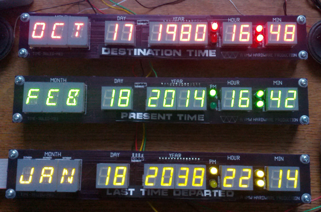
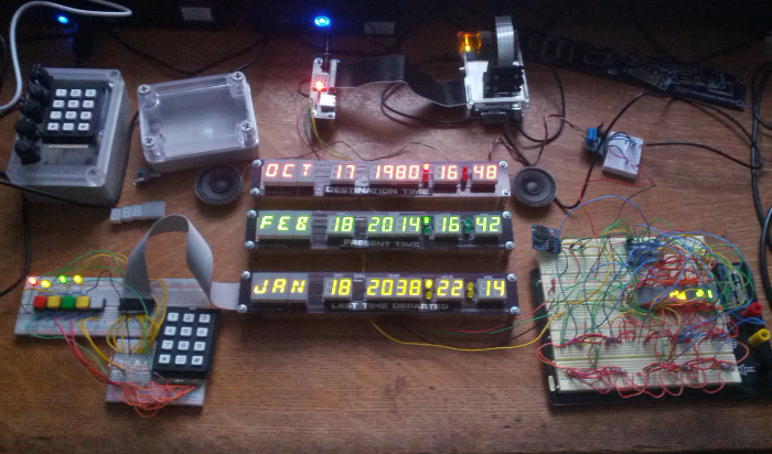
The goal is to have three calendar/clock displays (red/green/yellow)
that you can set via a keypad. In addition there is a flux
capacitor, a spedometer, various energy meters, and a
few other random features.
This is a hobby project:
full source code, documentation, and PCB gerbers are available free
for download.
Left to do:
Create a circuit board for the energy reading sensors.
Finish making it car mountable and powered.
Config the pi to actually use the i2c RTC.
Hook up to the car OBD port and get actual MPH readings on the display.
The Raspberry-Pi controls everything over i2c. The Pi (running
Linux) is a bit of overkill, as any board that can keep time and drive
an i2c bus could run things.
The display is run by a series of HT16K33 chips
(I use the breakout boards from adafruit).
Each chip can run up to 16x8 LEDs plus read a keypad matrix.
For the displays I use Kingbright common-cathode
LED displays.
I ended up buying direct from them as it was hard to source red, green, and
yellow displays of both 7-segment and 16-segment types
all from the same place.
In the end the yellow 16-seg are of type PSC05-12
and the red and green are of type PSC05-11 and the pinouts are not compatible.
This is unfortunate because it means I'll need separate PCB layouts.
Limitations
The displays will not match the version seen in the movie exactly.
There are some good reasons for that (
the month names as displayed in the movies aren't possible with
off-the-shelf LED displays).
Also I like to think Doc Brown himself was a bit of a hacker (although
a bit of a perfectionist) and thus any rebuild he did would vary
as he thought up improvements.
Features
Time display (destination, current, last)
Speaker for sound effects (and music!)
Numeric keypad and 5 lit buttons (the white enter button is possibly
the only one used in the movie, I assign functions to the others).
Time entry is similar to that in the movie, with the addition
of a cursor as otherwise it is easy to lose your place (even better
would be to put the date as you enter it, but that doesn't look
as cool). Also need error handling for invalid dates.
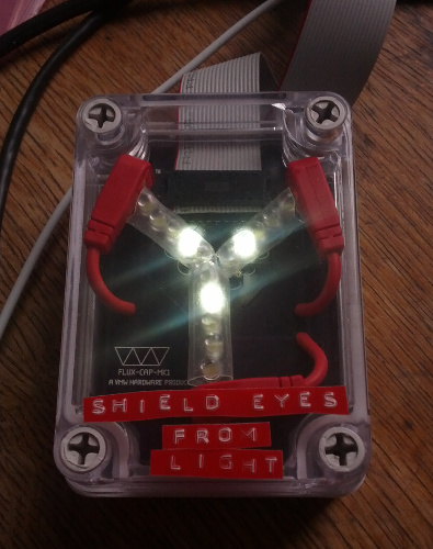
Flux capactior. Looks vaguely like the movie version though
much smaller.
Meter display, with one analog, one red/digital and one
red/green/yellow digital. Also an alphanumeric display capable
of printing current power reading. This is reminiscent of the
plutonium display in the movie.
Spedometer with accelerator and brake (no clutch or gear shift!).
Needed some way to trigger the time travel. Will likely
be grafted onto the meter display. Not sure best way to mount
buttons.
Real time clock. So it can remember current time even when not on
the internet.
Temperature probe. Why not?
Current Movies
Most recent movie showing current functionality.
Work has stalled for nearly a year due to other projects taking precedence.
I had wanted to have it car-mountable by the movie 21 Oct 2015 but not
going to happen. It does make a nice clock in my office, with which
to impress visitors.
Older Movies
Flux capacitor and power displays.
Note the analog and other meters as power-up happens.
Sorry for the backlit video, I need to build a case so I can angle
away from the window (or else find a better camera to record with).
Older demo including sound:
A much older run-through of the breadboard prototype
showing current time and then setting the date to various important times:
Perhaps be glad that you aren't taking the ECE471 Midterm this
Back-to-the-Future-Day:
16 October 2015
Have been lax about updating this log, but also have not had much
time to work on things.
Ironically it looks like I'm out of time for getting it working
by the 2015 BTTF2 date.
3 June 2014
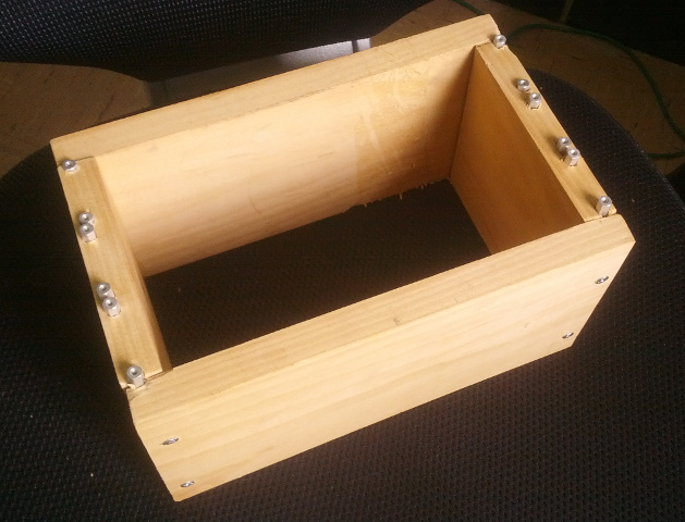
Prototype of the case assembled:
The case itself is made up of scrap wood and aluminum standoffs, with
holes (poorly) drilled by hand with a power drill.
Functional (barely) but not very pretty.
6 May 2014
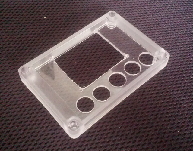
I finally got around to finishing and ordering the keypad PCBs.
I cut out the openings in the keypad case by hand.
Sadly they aren't aligned very well, despite the fact that I made
a paper template to guide the drilling.
Maybe time to get a CNC mill or at least a drill press?
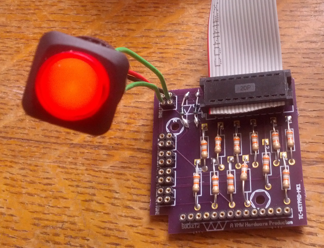
Testing the circuit board. The holes for the diodes were
way too small. In the end I sort of surface-mount soldered
them in place, I'm sure that's not good long-term.
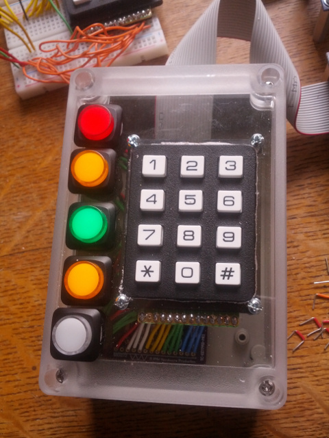
The assembled keypad. It was a pain getting all those wires in,
I should have used thinner wires and maybe socketed everything.
It works though!
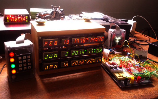
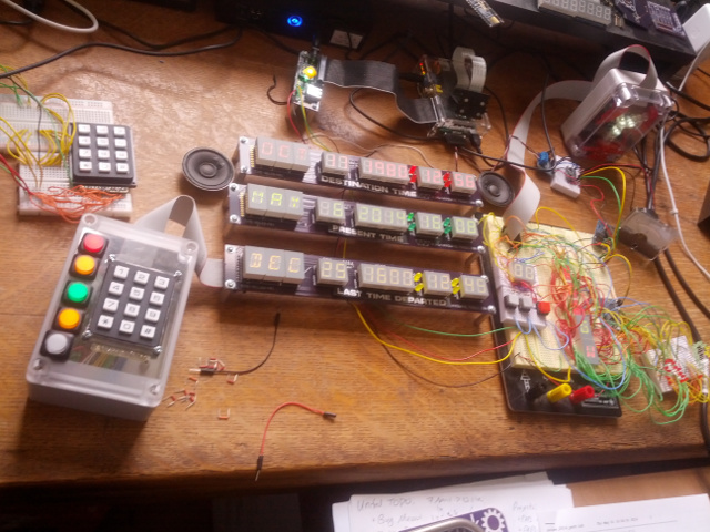
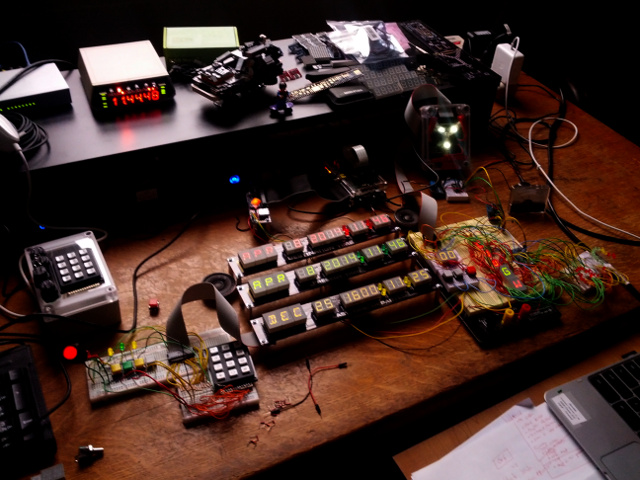
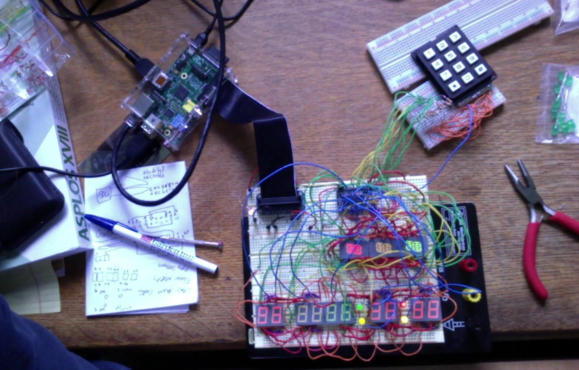
A snapshot of the current project area:
8 April 2014
The flux capacitor is more or less finished:
Flux capacitor and d/a board bringup:
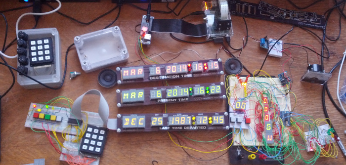
6 March 2014
The spedometer and flux capacitor circuitry as well as most of the power
display are functional. Waiting for a shipment of better LEDs, and then
I need to make some more circuit boards and drill holes in some cases.
26 February 2014
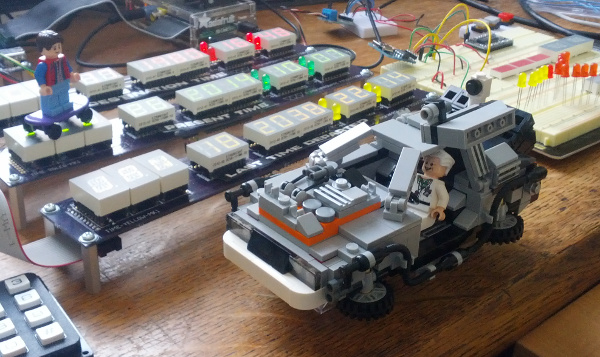
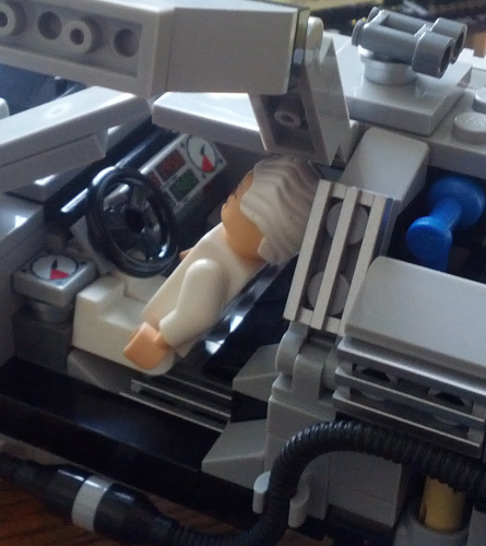
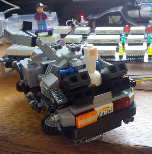
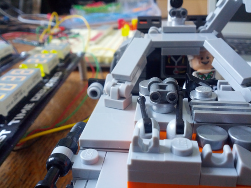
I had some visitors to my work area:
You can see the Lego time circuits. The date is set to 1958 when
the first Lego brick was made.
I couldn't decide on the old or new license plate. You'll note
I have Mr. Fusion installed, as well as the BTTF3 vacuum tube
circuitry. I'm using the old tires over the red whitewall ones.
That's a load-bearing flux capacitor. Also Doc's hair is too big
for the door to close while he's driving.
18 February 2014
Yellow display bringup, as well as the power-converter board.
Also took some time to clean up the keypad rats-nest.
12 February 2014
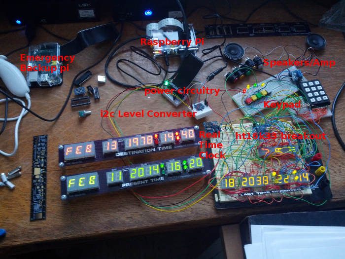
An annotated picture showing status at the time.
There's a battery-backed real time clock so you can keep time when
disconnected from the network. There's a speaker/amplifier for
sound effects and music. Also some power circuitry to bring in
a dedicated 5V/1A supply to the LEDs, as driving all of this from
the rasp-pi 5V output started getting dim and glitchy.
28 January 2014
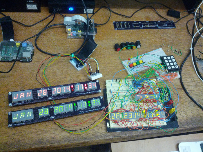
Bringup of the green display. It has the same layout as the
red display:
27 January 2014
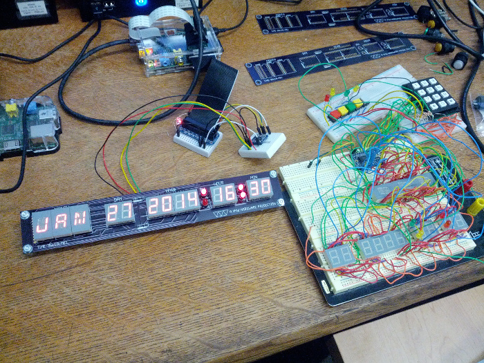
First bringup of the red display! Amazingly everything worked, except
for the 16-segs had segments R and S reversed due to lack of alphabetical
order in the data sheet (note the 'N' in JAN).
Easy enough to fix in software.
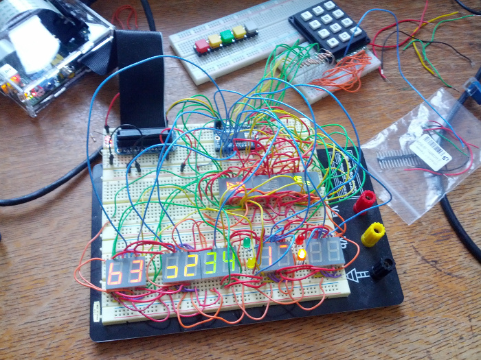
Time circuit malfunction! This is what I got after running the old software
on the breadboard after re-wiring to match the PCB version of the
display:
21 August 2013
First prototype of the display with all segments on as
a test. I have a mix of red/yellow/green just to be sure everything
is working.